In this document, we will address the settings of the Changeover Switch in the Chint Series N.
Please pay attention to the following points during installation:
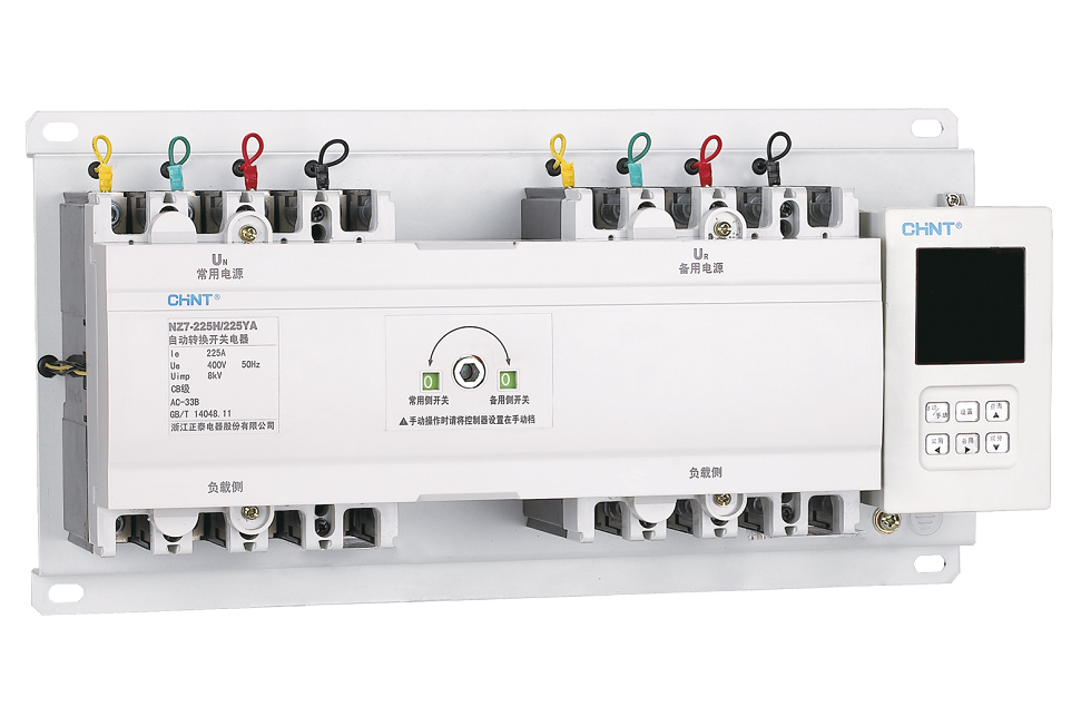
The left-hand switch corresponds to mains electricity, and the right-hand switch corresponds to the generator.
The input power of the switches must be from the top terminals, and the output from the bottom. In three-pole switches, the upper part is between the two neutral terminal keys, which must be connected to the mains electricity and generator neutrals via wires to these terminals. If the neutral wire is not connected to these terminals, the voltages measured by the controller will be incorrect, and the switch motor will not operate.
By pressing the AUTO/MANU button on the controller, the switch can be placed in automatic and manual modes, and both modes will be displayed at the top of the display screen.
In automatic mode, the switch operates the on/off function without the presence of an operator.
In manual mode, by pressing the N button, if mains electricity is available, the mains electricity switch will be connected, and by pressing the R button, if the generator input is available, the generator switch will be connected. By pressing the OFF button, the switch will be in the off position.
When the inputs are without power, using the dedicated handle provided with the switch enables the possibility of turning the switches on and off.
The switch display shows mains electricity voltages in the top row and generator voltages in the bottom row. If either of the switches is connected, the ON indicator in front of the voltage row lights up, and if disconnected, the OFF indicator. If the generator start blade is connected by the switch, the GENERATOR indicator on the electric Chint display at the bottom of the screen lights up.
Furthermore,
Pressing the SET button on the controller takes us into the settings menu. In the settings section, by pressing the left and right arrows (N and R), you can view settings A1 to A9, and in each section, by pressing the up and down arrows (QUERY and OFF), you can change the settings. The nine settings for the switch are as follows:
A1: Adjusting the mains electricity voltage reduction from 160 to 200 volts.
A2: Adjusting the mains electricity voltage increase from 240 to 290 volts.
A3: Delay time for switching from mains electricity to the generator, ranging from zero to 180 seconds (after the generator starts and reaches nominal voltage; in case of an error in mains electricity input).
A4: Adjusting the reduction of generator voltage from 160 to 200 volts.
A5: Adjusting the increase of generator voltage from 240 to 290 volts.
A6: Setting the return time from the generator to mains electricity (if mains electricity input returns to normal) from zero to 180 seconds.
A7: Setting the delay time for generator start from zero to 180 seconds.
It is worth mentioning that if a 24V DC power supply is connected to the switch, it is possible to adjust this section. However, if the 24V DC power supply is not connected to the switch, this setting will be zero seconds, and in case of a problem with mains electricity input, the generator start blade will be connected without delay.
A8: Adjusting the delay time for the generator to turn off after mains electricity input returns to normal and the mains electricity switch is connected, ranging from zero to 180 seconds.
A9: Setting the Input Types of the Switch:
If both switch inputs are mains electricity, this parameter should be set to 0.
If both switch inputs are from the generator, this parameter should be set to 1.
If the left switch input is mains electricity and the right switch input is from the generator, this parameter should be set to 2.
In the lower section of the controller, there are signal terminals described as follows:
Terminals 101 to 104 are related to mains electricity and indicate mains electricity input at 102, mains electricity switch connection at 103, and mains electricity switch trip at 104.
Terminals 201 to 204 are related to the generator’s status and indicate generator input at 202, generator switch connection at 203, and generator switch trip at 204.
Terminals 301 and 302 are intended for connecting a 24V DC power supply. If the power supply is not connected to these terminals, the switch will function normally, and only if the input power is interrupted or a fault is detected, the generator start delay time will be zero seconds.
If terminals 401 and 402, located in the lower section of the controller, are connected to each other, the switch will be in the off position, and to reconnect, terminals 401 and 402 must be separated, and one of the buttons on the controller must be pressed by the operator. Terminals 501 to 503 are related to the generator start. When mains electricity input is interrupted or experiences a fault, blade 502 is connected to 503, which can be used in the generator start circuit. When mains electricity returns to normal, after pressing the switch and the delay time elapses for turning off the generator, this blade is disconnected.