In the optimal selection of wires and cables, there are prominent and influential factors that require careful consideration. These factors include considerations such as the type of specific software needs, the intended usage environment, technical specifications including various features of wires and cables, and ultimately, installation and maintenance costs. Each application may have unique requirements, such as high-speed data transmission, resistance to specific environmental conditions, or even the provision of stable and reliable energy.
In conclusion, decision-makers should, considering the diversity of criteria and various factors, make intelligent decisions for choosing the appropriate type of wire and cable based on requirements and different capabilities. This way, they can optimize the performance of their system and make the best use of it. Fundamental Features of Cables
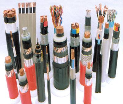
In the appropriate selection of cables for specific needs, it is important to pay attention to their main characteristics. These characteristics include nominal voltage and current, type of conductor along with cross-sectional area and shape specifications, core type, shielding type, insulation material, armor type, and corrosion protection type. Providing accurate and comprehensive information in these areas allows for the best selection of cable for projects and specific needs.
Determining Factors in the Selection of Suitable Cables
For optimal and high-performance cable selection, attention must be paid to several fundamental factors. These factors include the required load and cable capacity, nominal voltage, allowable voltage drop, circuit protection, short-circuit current, mechanical conditions, and environmental conditions, including temperature, pressure, tension, humidity, and cable installation effects. Additionally, specific technical specifications play a crucial role in this process.
To determine the cable cross-sectional area, special attention should be given to the consumer’s required current, cable tolerance to current, and allowable voltage drop. This information is crucial for improving the performance and efficiency of electrical systems.
Allowable Current of the Cable
In the transmission of electricity through wires and cables, an increase in temperature can lead to insulation failure. To protect the insulation, the generated heat must remain within its maximum permissible temperature. Heat transfer to the external environment occurs through conduction and radiation, depending on factors such as ambient temperature, final temperature, heat transfer coefficient, and cable characteristics. Therefore, accurately determining the allowable current requires addressing heat transfer issues.
In order to enhance the performance and efficiency of electrical systems, paying attention to the current intensity of the cable is of great importance. This value is directly related to the size and cross-sectional area of the cable wires and determines the thermal limitation resulting from the passage of current within the cable. Considering the insulation tolerance and thermal constraints, specific tables have been designed for various cable types, specifying the allowable current intensity for them.
The allowable current intensity for each specific temperature is calculated and specified in tables. Attention to the ambient temperature, cable installation location (whether in the air or underground), and installation method also significantly affect the determination of this value. Colder air has a greater heat absorption capacity, and heat transfer through insulation is more effective.
Allowable Current in Uninsulated Wires
Uninsulated wires are commonly used in overhead networks and must have sufficient mechanical strength to bear their weight and resist wind, ice, and snow pressures. For this reason, wires with a cross-sectional area of less than 6 square millimeters are often not used in overhead networks. An increase in temperature may also lead to a reduction in the tensile strength of the wire, so precise temperature control is essential for the optimal performance of the wire.
Current Ratings in PVC-Insulated Copper Wires
PVC-insulated wires are categorized into three groups: conduit wires, multi-layered air wires, and single-layer air wires. This classification aims to enhance efficiency and adaptability to different installation conditions.
Current Ratings in PVC-Insulated and Sheathed Copper Cables
PVC-insulated and sheathed copper cables are installed under two different conditions. These cables may be buried underground at a depth of 70 centimeters and a temperature of 20 degrees Celsius or installed in the air at a temperature of 30 degrees Celsius. The current ratings for these cables are calculated based on their cross-sectional area, and the maximum permissible temperature of the PVC sheathing is 70 degrees Celsius.
Current Ratings in Aluminum Wires and Cables
Aluminum wires and cables, with lower specific resistance compared to copper, have smaller cross-sectional areas. The specific resistance of aluminum is 1/6.5 times that of copper, leading to a reduction in the allowable current in aluminum compared to copper. This difference is determined by analyzing the power heat relationships generated in one meter length of both types of conductors, and the ratio of the allowable current in aluminum to copper is calculated.
In electrical concepts, current ratings and voltage drop are crucial aspects in power networks. Current ratings indicate the amount of current that wires and cables can safely carry with minimal risk. However, during the transmission of this current, voltage drop becomes a fundamental consideration.
Nominal Voltage
Nominal voltage refers to the value for which an electrical device is designed to operate optimally. However, the actual voltage experienced by equipment during its operational use may vary significantly compared to the nominal voltage.
Voltage Drop
In the design of electrical systems, calculating voltage drop from the source to the load location is crucial. Excessive voltage drop can have detrimental effects on equipment. Some of these effects include:
– In Motors: Voltage drop leads to a reduction in starting torque and maximum torque. This relationship is due to the squared dependence of motor torque on terminal voltage.
– In Incandescent Lamps: Voltage drop results in reduced light output and an increase in the lamp’s red spectrum.
– In Discharge Lamps: These lamps are not sensitive to low voltage drop, but excessive voltage drop may cause them to shut off.
– In Electronic Devices: Voltage drop can have significant effects, necessitating the use of stabilizers and regulators.
– In Electromechanical Equipment: Standards emphasize that if voltage decreases to a specific limit, equipment may not function properly.
According to standards, voltage drop from the source to the load should be less than 4%, with the exception that momentary voltage drop during motor startup or the transient effects of surges and transients are not considered.
Determining the conductor cross-sectional area in power networks depends on several crucial factors that ultimately have a direct impact on the system’s performance and efficiency. These factors include:
Type of Use (Single-phase or Three-phase): How the conductor is used influences and assists in determining the conductor’s structure.
Allowable Current: The current value that the conductor must transmit is of paramount importance.
Installation Conditions: This includes the type of installation (surface or concealed) and the environment (open or buried), which significantly affects the decision regarding the conductor’s structure.
Permissible Temperature: The maximum temperature at which the conductor must operate.
Voltage Drop: The maximum allowable voltage drop value.
Harmonic Effects: The effects of harmonic presence on the conductor.
Electromechanical Stresses: Stresses resulting from short circuits in the conductor.
Other Mechanical Stresses: Mechanical stresses that may affect the conductors.
Maximum Apparent Resistance: The maximum resistance value that the conductor must have for the proper functioning of protective devices in the face of short circuits.
These factors are indeed designed to protect electrical systems. However, from an economic perspective, there might be instances where larger conductor sizes than necessary for protection are used.
To ensure the safety and optimal performance of electrical equipment, having precise and complete technical information about conductors, including resistance, allowable current, and their tolerance capabilities under various conditions, is crucial.
Optimal Design of Electrical Systems
For the optimal design of electrical systems, calculating the cross-sectional area of conductors is one of the vital stages. These calculations are based on three main factors: the allowable current of the conductor, voltage drop, and losses along the conductor path.
The cross-sectional area should be chosen in a way that, in addition to carrying current under the most challenging conditions (considering the maximum temperature), the voltage drop and associated losses during the supply of energy to the consumer fall within the standard range.
To calculate the cross-sectional area of a cable, the transfer current capability, considering the resistance of the path, is used. These calculations involve formulas expressed as:
[A: text{Cross-sectional area in square millimeters}]
[L: text{Distance from the panel to the consumer in meters}]
[I: text{Consumer current in Amperes}]
[Delta U %: text{Allowable voltage drop along the conductor}]
[U: text{Line voltage}]
[P: text{Real power required by the consumer}]
[X: text{Conductor conductivity coefficient (56 for copper and 35 for aluminum)}]
In conditions where the ambient temperature exceeds 30 degrees Celsius or the distance between the conductors is less than twice the diameter of the largest conductor, thermal and adjacency coefficients should be considered. It is advisable to calculate the consumption current first and then, using the thermal and adjacency coefficients, determine the cross-sectional area of the conductors to avoid selecting a cross-sectional area larger than necessary.
Process of Electrical Installations Design
In the process of designing electrical installations, determining the cross-sectional area of conductors for consumers is of great importance. This determination includes details such as the diameter of the entry gland into the panel (if necessary), the cable tag number, and the required grounding conductor. For example, in a cable with a cross-sectional area of 16×4 square millimeters, a gland with a cable diameter of 23.5 millimeters and a tag number 16 for the grounding conductor are required.
To calculate the cross-sectional area of conductors within the panel, one must first determine the maximum current intensity required from the allowable current table of wires. Then, using fuses, switches, conductors, and other necessary devices on the single-line current path, the precise values of each of these elements are noted. Finally, by summing the power or current of each consumer, the total power consumption of the panel is obtained.
Information on the current drawn from the busbar, referring to the allowable current table of busbars, determines the dimensions of the required busbar. This information can also specify the power of the main switch and the total fuse on the blueprint. If the simultaneous coefficient of consumers is considered, design engineers apply these coefficients in power calculations using available references.
To calculate the cross-sectional area of conductors based on the allowable current, the first step is to determine the currents for both single-phase and three-phase systems since consumers can use both systems to meet their needs.
In modern residential buildings with a high number of units and the use of three-phase loads such as elevators and motor rooms, the need for high electrical power is common, necessitating the choice of three-phase cables.
The AWG standard stands for “American Wire Gauge” and is used for solid round wires. In this standard, the larger the AWG number, the smaller the wire diameter. This increase in wire diameter results in reduced resistance and increased conductivity characteristics of the wire.
Temperature and Conduction Effects on Cable Current Ratings
Temperature and conduction are among the factors that influence the permissible current of cables. Consider the thermal effects and current ratings in cables for better data transmission in electrical systems. There are various methods for calculating thermal requirements and current ratings in cables, including calculation methods considering thermal gradients, mechanical torque, and other related formulas.
Using cables in various conditions can lead to temperature changes and proximity to other cables, which can have extensive effects on the permissible current. Some methods of calculating the permissible current, considering these effects, refer to groups A1, A2, B1, B2, C, D, E, G, and F.
According to cable standards, the temperature effects on the permissible current of cables are considered in the specified environmental conditions. Typically, the ambient temperature is assumed to be 30 degrees Celsius.
For the proper selection of cables in variable temperature conditions, it is necessary to consider the cable heat increase due to higher temperatures, the presence of more units, proximity to other cables, and changes in ambient temperature, and perform the required calculations. These actions lead to greater accuracy in selecting suitable wires and cables for each condition.
The arrangement of various cable combinations based on conduction analysis and temperature rise is of particular importance. Adhering to the principles of cable arrangement in the system helps maintain the permissible current capacity and reduce temperature rise.
Maintaining Distances in Cable Arrangements and Voltage Drop Calculation
In the sequence of combining multi-core cables, observing the distances between them is of particular importance. If the distance between cables is at least as much as the outer diameter of the largest cable, the potential for temperature rise and proximity effects decreases. This action helps preserve the permissible current capacity and prevent efficiency loss in cables.
In specific conditions where extra-strong cables are used, attention to the arrangement of various cables is necessary to mitigate higher temperatures and proximity effects. These considerations are highly significant and play a vital role in increasing the lifespan and efficiency of cables.
Calculating the cross-sectional area of the conductor considering the permissible voltage drop is crucial. In low-pressure systems with two different voltages of 230 and 400 volts supplying consumer loads, voltage drop along the paths of loads may affect the performance of devices. The resistance and self-inductance coefficient in weak-pressure lines also contribute to voltage reduction. To prevent these issues and maintain the efficiency of devices, selecting the appropriate cross-sectional area for the conductors is essential. With this approach, determining the maximum permissible voltage drop, considering the network type, is of paramount importance to ensure optimal device performance.
Calculating Voltage Drop and Cross-Sectional Area for Three-Phase Circuits
In commercial and office buildings where single-phase loads are connected to a three-phase network, load balance is often not present. This situation leads the neutral wire to carry current as well. In this case, voltage drop is calculated by summing the voltage drops across the neutral and phase conductors with the highest current.
Electric Resistance in Wires and Cables During Alternating Current
In environments where electrical current flows in the form of Alternating Current (AC), the electrical resistance in wires is higher than the resistance observed in Direct Current (DC). This increase in resistance occurs due to inductive properties and skin effects, indicating the uneven distribution of current across the cross-sectional area of the wire. Frequency, structure, and size of the wire are among the factors that influence the magnitude of this increase.
At a frequency of 50 hertz, the resistance increase factor for a single-strand wire is approximately 1.02. This number increases to 1.05 for braided wires with a higher number of strands. Additionally, an increase in temperature leads to an increase in the specific resistance of copper.
In braided wires, the strands are twisted together in a helical pattern, causing an increase in the length of the strands except for the central strand with an insulated wire. This property significantly affects the calculation of the real resistance of the wire, requiring the use of different coefficients for single-strand wires and braided wires with multiple strands.
In multi-strand cables, considering the helical arrangement of the wires, the actual length of each wire is greater than the total length of the cable. Therefore, the use of different coefficients in calculating the resistance is essential for single-strand cables and multi-strand cables.
Influential Factors in Wire and Cable Selection
Nominal voltage, denoted as U0/U, represents the voltage that a wire is designed to withstand and is expressed in volts. The nominal voltage depends on the insulation state and thickness. U0 indicates the effective voltage between each wire strand and the ground, while U represents the effective voltage between two phases of the system from the wires.
Nominal Current Criterion
Nominal current is a constant value that flows through a conductor without a temperature increase up to a specified limit. The permissible current is dependent on the characteristics of the conductor, its type, and installation. If the cross-sectional area of the conductor is less than 10 square millimeters, the neutral conductor and the protective conductor must be separate. However, if the cross-sectional area is more than 10 square millimeters, a common conductor can be used for both the neutral and protective conductors.
When wires with a cross-sectional area below 25 square millimeters are used, the cross-sectional areas of phase, neutral, and protective conductors must be uniform. However, in wires with cross-sectional areas exceeding 25 square millimeters, the grounding conductor can be half the size compared to other conductors.
Low-Voltage Cables
Low-voltage cables are a special type of electrical cable that holds particular importance. In multi-core low-voltage cables, which are used as an option for four-core cables, the cross-sectional areas of the three larger cores are usually larger than the others, while the cross-sectional area of the fourth core is minimized.
Smaller wires may have different ratings in some cable sizes compared to other wires. These wires generally have lower ratings than other wires.
In both low-voltage and high-voltage cables, when larger cross-sections are required, the use of single-core cables is a common option. For example, in buildings, a three-core cable with a cross-section of 300 square millimeters may pose challenges in terms of outer diameter and twisting at sharp angles.
Multiple factors influence the lifespan of cables, and the usage conditions are one of these crucial factors. Cable installation on the ground must adhere to safety guidelines. Additionally, the bending radius of the cable should not be less than 15 times its outer diameter, and the temperature during cable installation should be no less than 5 degrees Celsius above zero.
Improving Efficiency in Closed Distribution Networks by Enhancing Voltage Drop
The use of multiple feed lines for consumers in both direct and alternating current networks holds great significance. Categorizing consumers on main lines based on their importance and activities under normal conditions is essential. When distribution networks have numerous branching feeder lines, the voltage drop at terminal branch points will be considerable.
One approach to reduce voltage drop in distribution networks is to feed from both ends. In this case, the minimum potential for voltage drop occurs only at a specific point, known as the “deep point,” and this reduction in voltage drop can resolve energy loss issues. The identification and determination of the deep point is highly crucial as a prominent aspect in auditing and calculations related to closed-loop networks. Some methods used to detect deep points include:
1. At the deep point, the maximum voltage drop occurs.
2. At the deep point, the network voltage reaches the minimum possible value.
3. At the deep point, the direction of the network current changes.
Closed distribution networks are fundamentally composed of two types:
1. Closed-loop networks with two power sources that are fed from both directions.
2. Closed-loop networks with a single power source, known as ring networks.
Enhancing efficiency in distribution networks using variable cross-sections provides a suitable platform for improving performance and increasing energy transfer efficiency. However, the use of these networks comes with specific challenges:
1. In distribution networks with variable cross-sections, increasing consumer power faces constraints.
2. The number of branches in these networks is not easily increased.
3. Connecting two parts of the network at points where the cross-section changes always presents technical challenges and issues.
Nevertheless, these networks offer considerable economic advantages, and the costs associated with the conductors used in them are significantly reduced. In summary, besides improving energy transfer, these networks enhance the cost-effectiveness of the energy transfer process due to reduced conductor-related expenses.
As a crucial factor in conductors, the skin effect plays a significant role in electrical current and conductivity of these materials. Conductors, recognized for their responsibility in carrying electrical current, are typically produced from copper, aluminum, or specific alloys. The design and cross-sectional surface structure of conductors vary based on different applications and needs. In electrical installations in buildings, copper with a purity exceeding 99.5% is commonly used as a conductor.
Copper is considered one of the primary choices for making conductors due to features such as low electrical resistance, excellent electrical conductivity, weather resistance, adequate mechanical strength, and malleability. Additionally, aluminum, with advantages such as suitable mechanical strength, malleability, lower electrical conductivity compared to copper, and lower cost, is used in some cases. However, aluminum also has drawbacks, including susceptibility to weather conditions that may lead to oxidation and a lower yield strength.
The skin effect in conductors describes how alternating current is distributed in regions near the surface of the conductor. This phenomenon is a result of the frequency of alternating current occurring at intervals from the surface to the skin’s depth, leading to an increase in the effective resistance of the conductor. Consequently, its electrical conductivity is affected.
Conclusion
In conclusion, this article has addressed various issues in the field of power distribution systems. Initially, it focused on calculating the cross-sectional area of conductors considering the permissible voltage drop in consumer loads in low-pressure systems. Subsequently, it examined voltage drop and cross-sectional areas of three-phase circuits, highlighting important points in this regard.
Furthermore, the article delved into the topic of electrical resistance in wires and cables under alternating current, elucidating the effects of the skin effect on the electrical conductivity of conductors. Finally, it explored issues related to closed distribution networks and variable cross-sections. This comprehensive and precise article provides the reader with valuable insights into the field of power distribution.