A push button or switch is a mechanism used to control the operation of a system or device. This tool is made of various materials such as plastic, metal, or bakelite to possess suitable resistance and hardness. Metal and plastic push buttons also have auxiliary contacts that enhance their performance. These tools, using their switch mechanism, enable more precise control over the desired system or device.
The surface of a push button, also known as a push button series, can have two levels: smooth and flat or concave. These shapes can include a protruding or domed state and sometimes feature a key to lock equipment. The design of this push button series is usually round or square, allowing greater flexibility in use and placement in various systems and devices.
The push button or push button series can be activated in several different ways, including:
– Surface pressing with a fingertip
– Deep pressing
– Tapping
– Punching
These various types of pressing allow for a diverse range of control when using the push button or push button series, from light fingertip pressure to deep pressing and even through tapping or punching.
What components make up a push button?
Comprising a piston, a return spring, and a set of contacts, the push button is recognized as a vital part of control units and electrical tools. There exist various models of these push buttons. For instance, a Normally Open (NO) push button, in its open state, does not allow current to pass. When no pressure is applied, the piston returns to the open state with the help of the spring. Additionally, Normally Closed (NC) push buttons are used to control circuit opening and closing. In the normal state, the contacts are closed, allowing current to flow in the circuit. However, by pressing the button, the contacts open, preventing the flow of current into the control circuit. These buttons are known as momentary connections because they are open until pressure is applied.
Functionality of Schneider Push Buttons:
Schneider push buttons feature an internal spring mechanism that performs the intended action under applied pressure and automatically returns to the initial state. For example, in the lockable model, after pressing, the push button gets locked, and with the rotation of the mushroom-headed series key, such as XB5AS542, in a clockwise direction, it is released and returns to the initial open state.
Schneider’s Diverse Push Buttons
In the lockable key-operated model such as XB4BS9442, by using a key installed on the mushroom-headed series, it’s possible to lock the push button, preventing any unauthorized pressing and operation. This usage is particularly crucial in operational vital zones to ensure access is only possible for authorized individuals.
The coding of push buttons is carried out based on specific colors assigned to them, preventing potential mistakes in button pressing by operators.
The XB4BW3165 push button has a chromium metal body and features a spring return function. This push button, in white color, is used for BA9s lamp without a lamp. It comprises one NO (Normally Open) contact and one NC (Normally Closed) contact, and the supply voltage for operating this product is less than 250 volts.
Start Push Buttons:
Schneider offers various types of push buttons used to control and interrupt contactors in electrical systems. These buttons are momentary switches that, upon pressing, move the spring blades, either connecting or disconnecting two contacts from each other.
Stop Push Buttons:
The functionality of these push buttons is typically carried out by human hands, but in some devices, they also utilize pedals (foot-operated controls) and mechanical movements of the machine (micro-switches). In control circuits, often two types of push buttons or switches are used: normally open (start) and normally closed (stop), or a combination of both. Below, the various types of Schneider push buttons will be closely examined.
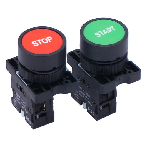
The start push button is a practical tool that, upon applying pressure or impetus, connects the contacts. This button is normally in an open state and closes upon short-term pressing or touching. There is a spring inside the start push button that facilitates its return to the initial state. Typically, the standard colors for start push buttons are green or black, although they might also be produced in various other colors.
Start-Stop Double Push Buttons:
The stop push button is a similar tool that, upon pressure or impulse, interrupts the connected contact. In its normal state, this button is closed and momentarily opens upon pressure. Inside the stop push button, there is also a spring ensuring its return, but the contactor circuit remains in a connected state using an auxiliary blade (normally open contact). In some cases, not using the auxiliary blade might result in instability in the circuit.
It’s clear that when we cut off the contactor through the stop push button, if the power supply is interrupted, the contactor circuit also gets disconnected. With the return of the electrical current, the contactor doesn’t automatically reconnect until we activate the circuit again using the start push button. The standard color for stop push buttons is red.
The Start-Stop Double, as a combination of the start and stop push buttons, is used in electrical systems. This type of push button is identified by a two-digit number indicating the number of open (start) and closed (stop) blades. For instance, a Double Start-Stop button numbered 11 comprises a single start button numbered 10 and a single stop button numbered 01. The number 32 represents a combined push button with five blades, indicating three start and two stop blades. The arrow direction on the push button symbols indicates the force direction for the spring’s return to the initial state. In electrical diagrams, devices are usually in the “Off Normal” state, and the blades make connections from left to right. If possible, connection diagrams are displayed vertically, especially for control circuits.
Structure of Schneider Push Buttons:
The structure of Schneider push buttons consists of a combination of a piston, a return spring, and a set of contacts. In the image, a normally open (NO) push button is depicted, which does not allow any current to pass when in the open state. When pressure is released from the push button, the piston returns to the open state with the help of the spring.
Normally closed (NC) push buttons are also used for opening and closing a circuit. In the normal state, the contacts are closed, allowing current to flow in the control circuit. By pressing the push button, the contacts open, prohibiting current from entering the control circuit. These types of push buttons are of the momentary connection type since the contacts remain open until pressure is applied to the piston.
Push buttons are designed in a way that when one push button is in the start position, it can act as a stop for another circuit. These buttons feature both normally open (NO) and normally closed (NC) contacts. In some cases, both types of contacts are used in a single push button. 22mm push buttons can control a maximum of 6 circuits, while 30mm push buttons can control up to 16 circuits in the most extensive configuration.
Schneider Push Button Color Codes:
Color codes are utilized for push buttons and indicator lights in building panels and control devices, where each color represents a specific meaning based on international standards like IEC-204-DIN 4818. These color codes provide information enabling various operations in control panels and devices.
Red-colored push buttons are used for stopping or halting operations. When these buttons are pressed, motors or operations are halted.
Mushroom-headed red push buttons are used for emergency shutdowns in control circuits and are paired with yellow labeling.
Green or black push buttons are used for activation or starting in devices. These buttons can connect motors to power sources or initiate specific functions in electrical devices.
Yellow push buttons are utilized for starting in non-normal situations, such as starting a motor in the reverse direction from the normal state or for movements avoiding hazards. By pressing these buttons, all previously connected parts are disconnected.
White and blue push buttons serve as multipurpose indicators for various other intentions and operate according to recommendations of international standards like IEC-204-DIN 4818.
Push Button Control Box:
The push button control box is an immensely effective tool for the quick and easy installation of manual control devices and signal lamps, including emergency stop buttons and other related items. This box allows for the installation of control buttons and signal lamps with a diameter of 22 millimeters, including products like the plastic green signal lamp with code (XB5AVB3) or the emergency mushroom-headed plastic button (XB5AS542).
Schneider’s control box design boasts high compatibility with the surroundings and full product recyclability, among its advantages. This product is recognized as part of the Premium green product range.
Schneider Electric’s control boxes are designed and manufactured based on various user needs, ranging from single-button to double-button and triple-button configurations. For instance, the product XALD02 from the Harmony XALD product line by Schneider Electric is a two-button control box without push buttons. This box is made of polycarbonate materials and features a light gray housing with a dark gray cover.
This product offers ease of operation, swift installation, an acceptable operating temperature range from 40 to 70 degrees Celsius, and an IK03 protection rating according to the EN 50102 standard.
Schneider Emergency Mushroom Push Button:
As one of the diverse electric push button products by Schneider, the Emergency Mushroom Push Button is a specialized model designed for emergency commands. This push button, part of the XB5 model range, includes a mechanical lock for emergency commands. The body structure of this product is crafted from plastic materials with silver alloy connections, and it operates within a voltage range of 120 to 600 volts AC or DC.
This particular emergency push button by Schneider functions similarly to a stop push button, being connected to a contactor. When the push button is pressed, the contactor is disengaged, triggering a warning.
With a 22-millimeter diameter and lacking a signal lamp, this product features a slow-break Normally Closed (NC) contact. One of the notable features of this emergency push button is its mechanical lock. Upon pressing the button, the product locks and can only be released from the locked position by turning the head in a clockwise direction. Therefore, it’s recommended to consider these features when installing this product in an electrical panel.
In the array of Schneider Electric’s diverse products, there are key differences between a push button, an emergency button, and an emergency stop button:
Emergency Disconnect Switch with Mechanical Locking:
This type of push button directly interrupts the circuit. The speed of opening the Normally Closed (NC) contacts and initiating the disconnect (OFF) command depends on the speed of pressing the push button, and sometimes, the disconnect (OFF) command may activate before the mechanism locks.
Emergency Stop Switch with Trigger Action and Mechanical Locking:
This kind of push button functions similarly to the emergency disconnect switch with mechanical locking, directly breaking the circuit. The speed of opening the Normally Closed (NC) contacts and generating the disconnect (OFF) command also depends on the speed applied to the push button.
To execute the locking mechanism and open the circuit via the NC contacts, the stored energy in the spring is utilized. This indicates that the locking mechanism only activates with the disconnect (OFF) command and the disconnect (OFF) command won’t be issued without the system being locked.
The limitations and standards related to the performance of push buttons and emergency disconnect switches in the industrial and machinery sectors hold significant importance. The use of safety components such as emergency disconnect switches complies with laws and standards like 2006/42/EC, EN/IEC 60204-1, EN ISO 13850, and IEC/IEC 60947-5-5. These standards emphasize that emergency switches must have the capability of applying locking and one of these components cannot function without the other.
The use of emergency switches in machinery and industrial devices is a significant method to reduce potential hazards. These standards prioritize the need for locking capabilities in emergency switches to mitigate risks such as electrical shocks or fire hazards in industrial environments.
The balance between emergency switches and locking mechanisms is crucial within these standards. While the use of a trigger mechanism in push buttons may not be obligatory, having this feature contributes to creating a safer work environment and reducing associated risks.
Conclusion
We’ve introduced an extensive range of push buttons and emergency switches from Schneider Electric. This review began by detailing various types of buttons, including start, stop, and double start-stop, explaining the functionality of each. Then, we delved into the study of the structure of push buttons and the value of using Schneider’s control box.
In another section, we highlighted the differences between push buttons, emergency switches, and emergency disconnect switches, examining their roles in emergencies and maintaining industrial device safety. This section concluded with an overview of standards and laws related to the performance of these components, emphasizing safety considerations in their installation and use.
In the final segment, we discussed Schneider’s push button color codes and explained how these codes are utilized in electrical panels and devices. This article has provided comprehensive information to enable the reader to ensure safety and adequate efficiency in their electrical systems by making informed choices and proper use of these tools.