Perhaps you have heard a lot about the earthing system by now. This topic has led us to fully explain it in this article. Please join us to obtain complete information about the earthing system.
Overview of the earthing system
As you know, electricity operates based on electrical potential or voltage. The potential difference between two points creates electrical energy, which then powers electrical equipment. This matter is particularly studied in the field of industrial automation.
In the power consumption system, there is a potential difference between phase and neutral or two non-homogeneous phases. In our country, this potential difference is 220 volts between phase and neutral and 380 volts between two non-homogeneous phases. Also, the potential difference between each phase and ground is considered, and the ground is considered as the zero-voltage point.
The earthing system is designed to conduct unwanted currents to the ground. All electrical equipment operates with voltage, and an increase or decrease in voltage can lead to fires and other hazards in electrical system circuits. Additionally, the possibility of electric shock exists in some cases.
If a human body comes between two points with a phase difference, such as phase and neutral or phase and ground, electric current passes through the human body and causes electric shock. For this reason, we utilize the earthing system so that if there is an electrical load in areas where there should be no electricity, the load is transferred to the ground.
What is the earthing system?
In many places, specific parts of equipment such as the body and areas that should not have electricity benefit from the earthing system. The duty of this system is to transfer voltage to the ground. To protect individuals and equipment, electric current always chooses the shortest path with the least resistance. For example, if the body of an electrical device is connected to an earthing pit, when our hand touches the body of this device, electric current passes through the body. The resistance of human bodies varies and depending on the dryness and healthiness of the skin and the physical characteristics of individuals, it ranges from 1 kiloohm to 100 kiloohms.
This principle applies to electrical circuits as well, with the difference that circuits may have less resistance than the human body. For this reason, the earthing pit must have the least possible resistance.
What is the purpose of implementing the earthing system?
In the past, until about 200 years ago, the concept of the earthing system did not exist, and no electrical equipment used this system. This led to many accidents and damages to individuals and the environment. However, in 1924, for the first time in England, the use of the earthing system became mandatory, and most places in this country benefited from this system. Today, the earthing system, as a fundamental principle in electricity, like electricity itself, has a wide range of applications. For example, in the field of telecommunications, earthing systems are used to prevent noise in the network, and they also have significant applications in power transmission and distribution networks.
Wireless earthless power grids are practically non-existent. For this reason, the primary objective of establishing this system is to prevent electric shock and associated hazards. This system is designed so that if any of the phase wires or the neutral wire connects to the body of the device and if there is leakage current in the electrical circuit, the leakage current is transferred to the ground via the earthing wire, preventing electric shock. Here, the most important objective of implementing the earthing system is to prevent electric shock and mitigate the associated hazards.
The main task of the earthing system is to completely transfer the incoming electric current to the ground. This earthing system consists of an earthing pit and a wire connected to the pit.
The general objectives of the earthing system include:
1. Containing currents generated from electromagnetic inductions and static electricity discharges.
2. Reducing step and contact voltages in hazardous potential difference situations.
3. Ensuring the proper functioning of protective equipment.
4. Protecting human lives and ensuring proper functioning for electrical, electronic, and digital systems.
Furthermore, the types of phases and three-phase systems in this system are classified as follows:
For phase conductors, L (Live) is used, for the neutral conductor, N (Neutral), for the earth conductor, PE (Protective Earth), and for the combined neutral and earth conductor, PEN (PE + N) is used.
Use of PEN (PE + N)
Types of single-phase grounding systems:
– Two-wire system: L1 + L2, L1 + N, L1 + PEN
– Three-wire system: L1 + N + P
Types of three-phase grounding systems:
– Three-wire system: L1 + L2 + L3
– Four-wire system: L1 + L2 + L3 + (N, PE, PEN)
– Five-wire system: L1 + L2 + L3 + N + PE
Types of grounding systems:
– TN earthing system includes TN-C, TN-S, and TN-C-S types.
– TT earthing system
– IT earthing system
– TN-C grounding system
In this system, the neutral and earth are common. In such a way that the neutral conductor is connected to the earthing pit, and then, using the PEN wire as the neutral conductor, it is also connected to the body for grounding protection.
– TN-S grounding system
In this system, the neutral and earth are separate. Although the neutral conductor is connected to the earthing pit, this connection only occurs at the distribution panel and at the starting point.
TN-C-S grounding system
In this system, initially, the neutral and earth use a common PEN wire and then, from a certain point onwards, they are converted into two separate wires named PE and N.
TT grounding system
In this grounding system, in addition to the separate neutral and earth wires, their conductors are also not connected to each other and are connected to separate earthing pits. In other words, the grounding system here has no connection to the electrical system.
IT grounding system
In this grounding system, either the energy source is not grounded or it is connected to the ground through a large impedance. Also, similar to the TT grounding system, the neutral and earth function separately in this system.
Bounding Grounding System
Bounding refers to connecting two electrical conductors to each other. These conductors can include pipes, wires, or cables. The primary objective of bounding is to ensure the equal potential of two pieces connected to each other. Thus, the possibility of electrical current flow between the two pieces is eliminated.
Furthermore, due to the equal potential, no current flows between the two pieces. Ultimately, the bounding path is connected to the ground to ensure that all equipment remains at the same potential as the ground.
The primary objective of the bounding system is personnel safety. In case of simultaneous contact with two pieces, no electrical current or shock enters the person due to potential difference. Another objective of bounding is protection in the event of a phase hitting metallic parts that may electrify it.
Under such conditions, the circuit fuse disconnects due to the system’s connection to the ground. In general, the primary objective of bounding is to equalize the potential of all metallic parts to prevent any unintended electrical discharge.
Grounding System
The earth is recognized as a large electrical conductor. Grounding involves connecting active parts (parts that normally carry electrical current) to the ground. This action is performed to protect electrical equipment and provide a path for the return of electrical current from the device to the power source.
Considering the dangers of lightning, voltage surges in lines, or unintentional contact with high-pressure lines, the possibility of dangerous voltage entering the electrical system is possible. Grounding provides a safe and alternative solution in residential and workplace environments to minimize potential damage.
Grounding wires are identified by their black color. The grounding system is used to protect circuitry against high voltage, lightning strikes, or unintended increases in load, while grounding serves as a common point for circuits to maintain voltage and provide a return path. The grounding system is used for human safety in unexpected situations, while grounding is used to protect equipment. Grounding provides a preventive measure, and grounding (Grounding) provides a return path for electrical current.
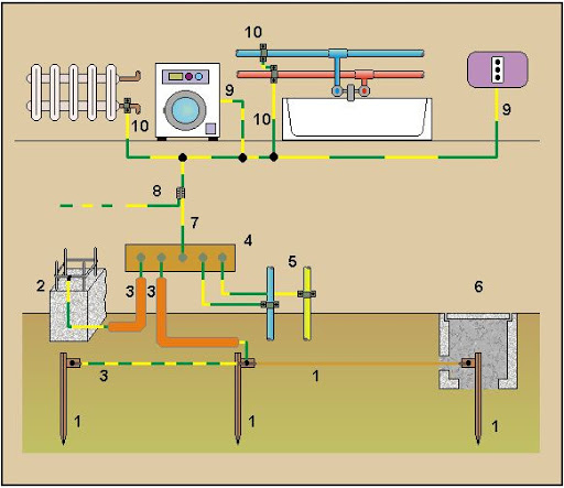
Methods of implementing the earthing system
There are generally two methods for implementing the earthing pit and protective system, and we will explain the use cases and required equipment for each method and how to implement each.
Spaces where the earthing system is implemented superficially:
1. Low altitude areas, such as northern and southern cities of the country.
2. The site’s post and surrounding area height is low.
3. Adequate space and the possibility of excavation around the site.
4. There is a considerable distance between the pole and the site.
Implementation of the earthing system by deep method:
1. Selecting the location of the earthing pit
The earthing pit should be placed in locations with the lowest level and where there is less moisture access at a lower depth or in areas more exposed to moisture and water, such as grasslands, gardens, and green spaces.
Depth of the Pit
Relative to soil resistance, the depth of the pit can range from a minimum of 4 meters to 8 meters, with a diameter of approximately 80 centimeters. In soils with lower resistance, such as agricultural and clay soils, the required depth for excavation is less, while in sandy and rocky soils with higher specific resistance, there is a need for deeper pits. Special devices are used to measure and obtain the specific resistance of the soil. If moisture has not been reached up to a depth of 4 meters and it is expected that moisture will not be reached beyond 6 meters, there is no need to dig the pit deeper than 6 meters. Generally, a depth of 6 meters and a diameter of about 80 centimeters are recommended for pit excavation.
3. Connection of the Wire to the Copper Plate
The connection of the wire to the copper plate is of utmost importance, and under no circumstances should this connection be established using clamps, wire stitching to the plate, etc. Instead, the wire must be soldered to the plate, and for additional strength, it should be secured to the plate using 2 wire clamps. Brass or silver solder is used to weld copper parts together, and if this type of solder is not available, Cadweld solder is used.
4. Earthing Pit Excavation
Considering the geographical conditions of the environment, a pit with a suitable depth and in an appropriate location must be excavated. Dig a trench 60 centimeters deep from the pit to the base of the pole for the path of the earthing wire to the pole’s lightning arrester. Also, dig for the earthing wire inside the building. If the path involves 2 common wires, it is better to isolate the paths of the two wires.
Also, the paths of the wires should be short, and the lightning rod and earthing wire should preferably be directly and without twisting or bending, and should not have sharp bends. If it is necessary to bend the wire, it should be bent over a length of more than 50 centimeters.
Filling the Earthing Pit
Initially, we prepare about 20 liters of saltwater solution and pour it into the bottom of the pit so that the entire bottom becomes damp. After 24 hours, we proceed with the following steps:
Fill the bottom 20 centimeters of the pit with clayey or soft soil.
Mix the required amount (about 450 kilograms equivalent to 15 bags of 30 kilograms each) of bentonite (soil resistivity reducer) with water to form a slurry and pour the resulting mixture to a height of 20 centimeters from the pit’s bottom. The thicker the mixture, the better the quality of the work.
Solder the copper plate to 2 copper wires, each of gauge 50, where one wire will be connected to the lightning rod on the pole, and the other to the internal building earth rod. Therefore, the length of the wires is chosen according to the length of the path.
Place the copper plate vertically in the center of the pit.
Surround the copper plate with the prepared slurry until it is filled above the plate.
Place the perforated polyethylene pipe obliquely in the center of the pit and above the copper plate, and fill the inside of the pipe with sand up to 50 centimeters from the end of the pipe. This pipe is for providing moisture to the bottom of the pit, and in hot seasons, water injection from this pipe is more common. It should be noted that in cases where the earthing pit is dug in the garden or the bottom of the pit is moist, or generally in places where moisture at the bottom of the pit is provided from above or below the pit, there is no need to place the pipe.
After placing the pipe, fill it with slurry up to 20 centimeters above the top of the copper plate.
Fill the remaining pit up to 10 centimeters below the top with regular soil mixed with sand or sifted agricultural soil. Fill the top 10 centimeters of the pit with sand and gravel for rainwater and surface water to penetrate into the pit. The top of the pit, especially in cases where the polyethylene pipe is not used, should not be asphalted or filled with cement.
Fill the drilled grooves with sifted agricultural soil or regular soft soil mixed with bentonite.
Installation of Grounding Rod and Lightning Rod
The grounding rod inside the building must be installed separately from the building walls using isolators. The diameter and length of the grounding rod depend on the number of branches inside the building. All equipment inside the building must be connected separately and in parallel to this rod. If the lightning rod is located on the building, the lightning rod wire should not be brought from inside the building. Instead, it should be pulled from outside the building, and the path for the grounding wire to enter the building up to the building’s entry ground rod must be insulated. At the base of the pole, the lightning rod wire should be securely connected to one of the pole’s foundations using a clamp and connected to the lightning rod at the top of the pole. It should be noted that the path of the lightning rod wire must be separate from the cables leading to the terminals.
Components of the Surface Grounding System
There are seven methods for implementing the surface grounding system:
1. ROD
2. RING
3. STAR
4. MIXED
5. ELECTROCHEMICAL
6. SPIRAL
7. NETWORK
Important Points Regarding the Grounding System
1. All connections should be welded with brass or silver wire. The weld surface must reach at least CM 6, and the direction for connections and welding must be observed. In special cases, the use of Cadweld is also recommended.
2. From each self-supporting tower base, both the tower foundation and the tower base should be welded to the grounding system using a copper wire and a special clamp.
3. The lightning rod wire should be connected directly to the ring inside the channel without bending, starting from a base with fewer antennas installed and having maximum distance from the cables on the ladder.
4. The lightning rod on the tower should be placed at the highest point of the tower (while observing a protective cone with a 45-degree angle) and should be constructed to fully cover the equipment. Its material should be entirely copper with a standard alloy diameter of 16 mm, and its length should depend on the height of the antennas installed on the tower.
5. The bending radius of the copper wire should be at least CM20, and the arc angle should be at least 60 degrees (observing the bending angle of the copper wire).
6. The tower bases and the starting and ending points of the horizontal ladder should be connected to the ground system.
7. All input cables to the equipment room should be grounded to the tower body and the beginning of the horizontal ladder (after the cable bending point) using a ground clamp.
8. Under no circumstances should welding be performed on the tower.
Connecting the Ground Network to the diesel generator fuel tank, the aerial water tank, the metal frame of the building, and inside and outside the windows of the equipment room should take place.
If a system has been previously installed, the old system should be connected to the new system at the soil depth. The ground wire at ground level should be insulated, and the wires inside the channels should be uninsulated and drawn directly. The channels should be filled with sifted agricultural soil or soft soil. The installation height of the copper bar should be at least 50 centimeters above the finished floor level. The grounding bar inside the room should be placed as close as possible to the arrangement of the devices. From each device, the ground wire should be separately connected to the grounding bar (the diameter and length of the grounding bar depend on the number of branches). In high-capacity guyed masts, the guy wires must be connected to the ground by a dedicated ground clamp. For using the city power transformer in telecommunication stations, a separate ground should be implemented. In computer sites, it is better to use a uniform ground surface (without slope) for the grounding system. There should be no voltage difference between neutral and ground at the stations. In high-dimensional masts where the mast height is more than 2 meters, installing an additional lightning arrester on the opposite side of the first lightning arrester is necessary. For wiring inside computer site compounds, use underground cables for lighting and other purposes, and do not use street lights in stations located in mountainous and remote areas. The acceptable standard for testing and delivering ground connections for small sites is less than 10 ohms and for large and vital sites is less than 3 ohms.
We thank you for staying with us until the end of the article. For ordering industrial electrical equipment at the lowest prices, you can contact ElectroShield’s experts.