Inside electric generators, voltage is generated through the magnetic flux associated with a coil. The phenomenon of electromagnetic induction shows that when a coil is placed in a varying magnetic field, an electromotive force is produced. Changes in the magnetic field can result from alternating current or the rapid movement of the coil within the magnetic field.
There are two methods to create changes in the magnetic field: first, the magnetic field can move around a stationary conductor. Second, the conductor can move within a magnetic field, causing variations in the magnetic field lines, which in turn induces an electric current in the coil.
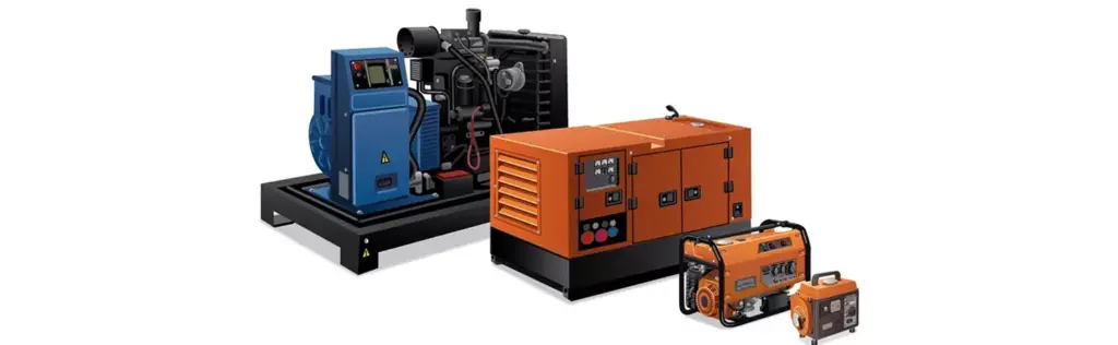
Components of a Generator:
1. Engine:
– The generator engine acts as the primary mover, converting fuel into mechanical energy.
– Various types of engines can be used, such as reciprocating engines, steam engines, turbines, and microturbines.
– The engine can run on fuels like gasoline, diesel, natural gas, propane, biodiesel, water, sewage gas, or hydrogen.
2. Generator:
– The generator converts the mechanical energy produced by the engine into electrical energy.
– The construction of the generator includes a stator and a rotor, generating an electromagnetic field.
3. Fuel System:
– The fuel system comprises a fuel tank, fuel pump, fuel filter, and injector.
– This system is responsible for collecting and transferring fuel from the tank to the engine.
4. Voltage Regulator:
– This component is used to regulate and control the voltage produced by the generator.
– The voltage regulator ensures that the output voltage remains consistent and stable.
5. Cooling and Exhaust Systems:
– The cooling system prevents overheating and regulates the temperature of the generator components.
– The exhaust system is used to expel harmful gases produced during fuel combustion.
6. Lubrication System:
– This system is responsible for keeping the moving parts of the generator well-lubricated by injecting oil where needed.
– Regular oil changes and monitoring oil levels are crucial for optimal operation.
7. Battery Charging System:
– The battery is used at the beginning of the generator’s operation to start the engine.
– The battery charger is responsible for charging and monitoring the battery level.
8. Control Panel:
– The control panel manages the electrical operations of the entire generator system.
– It oversees and regulates voltage, current, frequency, and other critical parameters.
9. Main Frame:
– The main frame or chassis of the generator engine is the primary structure that houses all the above components.
– This frame can be portable or stationary and encompasses all the equipment.
Read more: Review of Various Pneumatic Key Accessories and Their Applications
Differences Between Salient Pole Rotor and Smooth Pole Rotor
Electric rotors are divided into two types: salient pole rotors and smooth pole rotors. In a salient pole rotor, the poles protrude from the rotor surface, and these types of rotors are usually employed in generators with 4 or more poles. On the other hand, in a smooth pole rotor, the poles are flush with the rotor surface and are mainly used in synchronous generators and 2 or 4-pole turbogenerators.
Salient pole rotors are commonly used in hydraulic and multipole low-speed generators, such as those in hydroelectric power plants that require low speeds. However, smooth pole rotors are utilized in high-speed generators. These rotors are suitable for machines that require high-speed operation. The diagram below precisely illustrates the structural differences between a salient pole rotor and a smooth pole (hidden pole) rotor in a generator.
Types of Generators
Generators are broadly classified into two categories: AC and DC generators.
AC Generator:
An AC generator, or alternator, is a device that converts mechanical power into AC electrical power. This type of generator is designed to produce alternating current with a frequency of 50 or 60 Hz. The structure of an AC generator includes a conductor or loop of wire within a magnetic field produced by an electromagnet.
Both ends of the loop are connected to slip rings, which are in contact with two brushes. These rings supply current to the circuit through the brushes. When the loop is rotated, it cuts the magnetic flux lines, first in one direction and then in the opposite direction.
When the loop is in a vertical position (zero degrees), the coil moves parallel to the field and does not cut the magnetic flux lines. At this moment, no voltage is generated in the loop. However, as the coil rotates counterclockwise, it begins to cut the magnetic flux lines in the opposite direction, resulting in voltage generation.
The Direction of Induced Voltages Depends on the Movement of the Coil:
The direction of the induced voltages is directly influenced by the direction of the coil’s movement. These voltages are summed in series such that slip ring X acts as the positive pole (+) and slip ring Y acts as the negative pole (-). Consequently, the potential across resistor R causes electric current to flow from Y to X through the resistor.
When the coil is positioned horizontally relative to the magnetic lines (at a 90-degree angle), the current reaches its maximum value. This occurs because the coil moves perpendicularly to the magnetic field, cutting through the maximum number of magnetic flux lines.
As the coil continues to rotate, the induced voltage and current decrease until they reach zero when the coil returns to the vertical position (180 degrees). During the second half of the rotation, the voltage reverses polarity (270 and 360 degrees). This polarity change, with the 360-degree rotation of the coil, results in the production of an AC sine wave.
DC Generator:
A DC generator is another type of generator that converts mechanical energy into DC electrical energy. The induced current created in the armature conductors is initially alternating and is converted to direct current (DC) using a commutator (a cylindrical conductive slip ring).
In DC generators, the commutator plays a crucial role in converting alternating current to direct current. This conductive ring is designed to continuously switch the current poles, producing a stable DC current. As the armature rotates in the magnetic field, the induced voltage in the armature conductors is converted to direct current by the commutator.
This process makes DC generators highly suitable for applications requiring direct current, such as battery charging and powering DC electrical systems.
A commutator is a cylindrical conductive ring with slots that is attached to the armature, creating changes in the current. In a DC generator, the commutator’s job is to take the current produced by the rotating armature and deliver it as direct current to the load. In other words, the commutator in a DC generator is responsible for collecting and directing the current. Brushes in the DC generator take the current from the commutator and transfer it to the external circuit.
In the structure of a DC generator, both ends of the wire loop are connected to the commutator. As the wire loop rotates in the magnetic field, the slotted commutator moves, and each half of the slotted ring makes contact with the brushes. The brushes establish the connection between the external circuit and the rotating wire. The amount of induced voltage varies depending on the angle of the wire’s movement relative to the flux lines, as the number of flux lines cut by the wire depends on its angle of movement.
The process works as follows: as the armature rotates in the magnetic field, the induced current generated in the armature conductors is alternating. The commutator converts this alternating current into direct current and sends it to the output circuit. This feature makes DC generators highly suitable for applications that require direct current, such as battery charging and powering DC electrical systems.
The commutator is designed to continuously switch the current poles, producing a stable DC current. As the armature rotates and changes its angle relative to the magnetic field, the induced voltage varies. The commutator manages these changes to ensure a steady direct current output.
During the second half of the rotation, the brushes switch to the opposite segments of the commutator, ensuring that the polarity of the output voltage does not change. By increasing the number of loops to two or more, the average voltage increases, resulting in a smoother ripple.
Equivalent Circuit of Independently Excited DC Generator
In the equivalent circuit of an independently excited DC generator, a new innovation is applied that is entirely different from conventional methods of generating direct current. Here, electricity is independently transferred from the armature circuit to the excitation circuit. The excitation winding is fed by an independent voltage source, improving the electrical connection between the armature and excitation circuits.
This type of circuit enhances the efficiency of the DC generator and prevents additional complexities in electrical connections. This innovative method improves electrical transfer between circuits and represents a significant advancement in new energy technology research and development.
Applications of Independently Excited Generators
Independently excited generators are widely used in various applications due to their high voltage stability against changes in load current. These generators maintain a constant voltage, making them ideal for use in power plants and for providing excitation to AC generators. They are also highly effective in battery charging processes. This versatility highlights the efficiency and reliability of independently excited generators, marking a significant innovation in the transmission and generation of electrical energy.
The Latest Invention in Technology: Equivalent Circuit of a Shunt DC Generator
In this new generation of generators, the excitation winding circuit is connected in parallel with the armature winding circuit. This innovative model, known as a shunt DC generator, has broader applications compared to independently excited generators. The shunt generator operates without the need for an independent voltage source for excitation, as both the load current and the excitation current are supplied by the armature winding.
Additionally, more current flows into the armature winding of the shunt generator compared to independently excited generators. Consequently, the voltage drop due to the armature winding resistance and the armature’s magnetic effects is higher in this type of generator than in other models.
The applications of shunt DC generators are also very diverse; these generators are used for battery charging and for providing efficient excitation to power plant generators. This innovative invention has elevated energy transfer to a new level of efficiency and productivity in the electrical and energy industry.
New Advancement in DC Series Excitation Generators
In the category of DC generators, the series model with a new method of excitation circuitry has been introduced. In this model, the excitation circuit is connected in series with the armature circuit, creating a direct interaction between the excitation winding current and the armature current. This unique coordination provides the necessary voltage for the excitation winding.
DC series excitation generators, due to their simple structure and high efficiency, are used in various applications. These generators are suitable for providing stable and reliable power in different electrical systems, including battery charging and powering electrical devices. This new technological advancement has elevated the efficiency and productivity of DC generators, revolutionizing the electrical industry.
Applications of Series DC Generators
Series DC generators can be applied in specific areas. Due to their voltage instability with respect to load changes at the terminals, these generators are not suitable as a constant voltage source and require a high degree of voltage regulation. These characteristics mean that series DC generators have certain limitations and are used in limited applications.
Advanced Technology in Compound DC Excitation Generators
In the field of DC generators, new innovations known as compound DC excitation generators have been introduced, which are divided into several subcategories based on the connection method of the excitation windings.
Cumulative Compound Generator:
This type of generator has an excitation winding connected in series with the armature winding and an additional shunt excitation winding. This unique combination allows for the production of a constant and stable voltage.
Types of Compound DC Excitation Generators
Short Shunt Compound Generator:
In this type, the excitation winding is connected in series with the armature winding and a short shunt excitation winding. These configurations are useful for reducing voltage fluctuations during load changes.
Long Shunt Compound Generator:
This generator has an excitation winding connected in series with the armature winding and a long shunt excitation winding. These settings are designed to produce voltage with minimal fluctuation suitable for varying loads.
Series Field Adjustments for Precise Voltage Control:
In this generator, the excitation winding is connected in series with the armature winding and a short shunt excitation winding. This combination is suitable for applications requiring precise voltage control during load variations.
With these technological advancements, compound DC excitation generators provide greater versatility and efficiency in energy transmission. These generators, with their adjustable voltage capability and high stability, are highly suitable for various applications such as power generation systems, power plants, and industries requiring precise voltage control. Innovations in these generators have enabled improved performance and increased efficiency in energy transmission and distribution.
Single Phase Generator Technology and Winding Adjustments
In the realm of energy, single-phase generators (alternators) play a fundamental role in producing AC alternating current. These generators generate sinusoidal voltage by having a wire loop move uniformly in a magnetic field with uniform flux density.
However, generating appropriate flux density when there is a large air gap between the field’s two poles can be challenging. This results in low voltage production in the generator, making this configuration impractical.
Structure and Operation of AC Generators with Stationary Rotor
In this type of generator, the field poles are mounted on the movable part of the machine, namely the rotor, and the current for its windings is supplied through brushes and slip rings from a DC source. The rotor is rotated at a constant speed by an external agent. The number of poles in the machine (which are always even) depends on the rotor speed and the frequency of the stator windings. For example, for a 6-pole machine producing 60 Hz voltage, the rotor speed must be 1200 revolutions per minute.
In this machine, the armature winding is stationary, and its concentrated windings are interconnected in such a way that the induced voltages in all of them are summed up to form the final voltage.
By placing a variable resistance in the DC supply line, the excitation current of the poles can be adjusted, thereby controlling the flux density and consequently the output AC voltage.
These adjustments have contributed to improving the performance and efficiency of generators, enabling more stable and reliable power generation. The innovations in this technology have paved the way for further advancements in energy production and management.
Advanced Technology in Single Phase Generators and Structural Optimization
Currently, the structure of single-phase generators is not yet optimal because the windings of each pole are concentrated in a single slot in the stator and are not optimally utilizing the volume and internal environment of the stator. In commercial machines, there are more slots in the stator, and the windings are distributed in these slots.
Applications of Large Single-Phase Generators
Large single-phase generators are typically not mass-produced on a commercial scale and mostly range in power from 1 KVA to 5 KVA. These devices serve as emergency power sources for portable equipment or as home backup generators during power outages. Single-phase generator units, combined with a gasoline engine, are available in both portable and stationary forms.
Two-Phase Voltage Production
In this type of generator, another coil is connected to two additional slip rings, with both ends connected to each other. In a two-pole machine, there is a 90-degree mechanical angle between these two rings. When the voltage in the first ring is at its maximum, the voltage in the second ring is zero, and vice versa.
These advancements in single-phase generator technology enable more efficient solutions for generating and supplying electricity in various environments.
Three-Phase Generators with Six Conductor Coils
Three-phase generators with six conductor coils are positioned in a variable magnetic field and produce three-phase voltages with a 120-degree angular separation from each other. The structure of these generators places three coil windings on a common axis, creating a 120-degree angle between the starting point of each winding and the next coil. Slip rings are also part of this structure. By connecting one terminal of each coil as a common point or neutral point to each other, and connecting the remaining three terminals to three slip rings, they can be isolated from the machine. This type of connection is known as Y or star connection.
The current article provides a detailed analysis of the structure and operation of AC and DC generators. Initially, it explains the physical principles and the method of generating alternating current in AC generators. It then discusses DC generators and how they produce direct current using a commutator. Various types of generators, including separately excited and shunt types, are also examined. Finally, some applications of these generators, particularly in power plants and battery charging, are discussed. These analyses and explanations contribute to a better understanding and practical application of this technology in the electrical industry.